See
change log at bottom ! 07.06.2013 15:57:24
Overview
The jFEX processor system performs jet, large tau,
missing-ET and total-ET trigger algorithms on 0.1 × 0.1 electromagnetic and hadronic
towers, as described above. The jFEX system (see fig. x) consists of a single
AdvancedTCA (ATCA) shelf, equipped with several module types and is fed by an
optical fibre plant. The fibres are routed via rear transition modules into
jFEX modules, where physics algorithms are run. Timing distribution, ROD and
control hub functionality are implemented on two hub modules located in the
“fabric slots” of the shelf.
Each jFEX
module processes a phi-octant of calorimeter data, covering a strip along eta,
comprising barrel, both endcap, and forward calorimeters. A total of 8 jFEX
modules is required for full coverage of the calorimeter solid angle.
Jets and taus are identified on the jFEX modules as
local maxima of energy deposits in a window sliding over the detector space,
within an environment of 0.9 x 0.9 in eta x phi. This requires that each jFEX
module is supplied with a copy of the data from neighbouring phi-octants. The
data duplication is performed at the data source, the Digital Processor System.
A diagram of the jFEX module is shown in fig. x.
Real-time
data path
Real-time input data from the Digital Processor
System (DPS) and the legacy processors enter the jFEX module from the back, via
the rear transition module (RTM). The RTM is a passive circuit providing the
mechanics for feeding fibres into the jFEX module on 72-way MTP/MPO connectors.
Using standard opto backplane connectors, there is space for four of them in
ATCA zone 3. That allows for a total of 288 incoming fibres per module.
On the jFEX module the four fibre bundles are each
split up into six twelve-way ribbons that are terminated into “MicroPOD”
electro-optical devices. The devices support data rates of up to 14Gb/s per
fibre. The MicroPODs require custom-built mechanics to provide mechanical
stability and to spread the heat dissipated by the devices. The input signals
are routed on to the processor FPGAs as differential, CML level signals. Here
they enter the “GTH” high speed receivers and are processed in the FPGA fabric
after de-serialization to the LHC bunch clock frequency.
The processor FPGAs identify and report the trigger
objects (TOBs, i.e. jet and tau candidates) and calculate global quantities
(missing Et). The data reported by five of the processors on their fabric
interface are consolidated and merged in the sixth one before being sent out
optically via MicroPOD devices, on to L1Topo. So as to be able to duplicate
data into more than one L1Topo module, two MicroPOD devices (i.e. 24 optical
fibres) are allocated for that purpose. The fibre bundles are routed through
the front panel of the jFEX on standard MTP/MPO connectors.
Signal
duplication
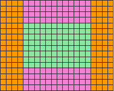
At an environment of 0.9 x 0.9 the sliding window
algorithms requires neighbour data of 4 cells to either side of each core cell
to be processed (see fig.x). Due to 100% data duplication of all signals at the
DPS, all environment required for processing the core cells of one calorimeter
octant is routed onto each jFEX module. The algorithms are partitioned to run
in six FPGAs per jFEX module. Each of the FPGAs needs access to the core cells
it processes, and the environment of +/- four cells. Therefore a large amount
of data needs to be duplicated between neighbouring FPGAs.
For inter-FPGA data duplication the baseline design
makes use of the “PMA loopback” scheme, as described in the eFEX section: All
incoming data are routed point-to-point into one FPGA receiver. After a short
latency penalty of just over one bunch tick the data are routed out of the
corresponding transmitter, on to the neighbouring FPGA.
The data are transmitted 8b/10b-encoded at 6.4Gb/s
line rate. As outlined in sect. x the net data volume of 128 bit per bunch
crossing per fibre allows for transmission of eight energy samples on each FPGA
input channel, including a checksum. Data are organized in 0.4 x 0.2 in eta x
phi per channel. Two samples, electromagnetic and hadronic energy, are required
for each trigger tower.
A single large FPGA with 80 input channels can thus
receive a maximum of 20 * 16 trigger towers. This is 12 * 8 core cells plus
environment data. Due to irregularities in the calorimeter overlap region and
in the FCAL area the mapping needs to be specifically implemented at PCB level.
Two of the jFEX processor FPGAs will actually have to be larger, and more expensive,
96-channel devices, so as to cover the overlap region. Out of the devices
currently on the market, the Xilinx devices XC7VX690T and XC7VX1140T appear
well suited for the jFEX module. For reason of latency, the fastest speed grade
available will have to be chosen for the real-time processors.
Timing
All real-time data transmission and processing is
performed synchronously at multiples of the LHC bunch clock. The clock as well
as TTC control data are received in backplane zone 2 on two signal pairs each
from the hub modules. Either hub can be selected to act as a clock source.
After signal conditioning (jitter reduction) and frequency multiplication the
clock is routed on to the high-speed link circuitry and into the FPGA fabric.
Readout
Readout and data transmission to the 2nd
level Trigger are implemented as described in the eFEX section. Processor data
are read out into two hub modules on six high-speed links each (one link per
processor FPGA), allocated in ATCA Zone 2. Recent ATCA backplanes support data
rates of up to 10Gb/s. This data rate is supported by the processor FPGAs, and
is sufficient for readout of both incoming and internal data. In normal running
the input data are expected to be read out only in the unlikely event of
checksum mismatches on the received real-time data.
Configuration,
Control, monitoring and diagnostics
The real-time processors will be configured upon
power-up through the control FPGA. The configuration bit stream will be stored
locally on an SD card. The control FPGA itself is configured via an SPI flash
device and the control firmware includes the algorithms to read and write the
SD card and sequence the configuration data into the processor FPGAs.
For module control the IPBus firmware suite is
employed. The base interface in backplane zone 2 is routed to an Ethernet phy
device, controlled by the control FPGA. Here a small footprint IP stack is run
directly in firmware. IPBus firmware maps Ethernet control and monitoring
packets to a processor-like bus interface, which in turn reads and writes
“registers” inside the FPGA. This access path is used to control and monitor
the operation of the processor FPGAs. Parameters for the algorithms are set,
and control of the high-speed links is performed that way, playback- and spy
memories attached to the real-time path are exercised, and the environment
(temperatures and voltages) is monitored.
Low level ATCA compliant control is achieved by an
ATLAS standard IPMC module.
Options
The baseline design described above allows for the
determination of jets and large taus in an environment of 0.9 x 0.9 in eta x
phi. This is an acceptable balance of physics needs versus achievable system
density and signal integrity. There is a very strong motivation though to work
towards considerably higher input data rates, which allow a move towards
significantly larger jet sizes. R&D projects have been started to validate
the feasibility and derive limits on data rates in dense electro-optical
systems with very high channel counts and in conjunction with data duplication
schemes. The jFEX system has been designed to fully benefit from an increase in
transmission speed to maximise the jet size.
Phase
II
The jFEX system is built such that it can be
operated as part of the L0 trigger after the phase-2 upgrade. The real-time
data path and the processing are expected to run unchanged, though the sliding
window algorithms might be upgraded. The chosen processor FPGA types are
providing enough logic resources to allow for algorithmic upgrades.
In phase-2 the distribution of clock and timing
signals is expected to change, as is the readout. These functionalities are,
however, not handled on the jFEX modules directly. Any modifications required
would affect the hub module mezzanines only.
3 drawings: system, jFEX, duplication scheme
Captions:
The jFEX processor system
jFEX module and major components
Processing area of 12*8 core cells (green) and the environment
received from DPS (magenta) and duplicated on jFEX module (orange)


Change log:
07.06.14:20 major rework.
06.06. 17:32 added initial versions of drawings.
Still working on that !
06.06. 17:18 changes in 1st para to
better distinguish jFEX system and module.